Signalling Runthorne, London Road.
By Dennis Mulhair, Egham & Staines Model Railway Society, 2003
This Article was written in 2003 to explain the working signals on our previous layout. Working signals to this design will be installed on Colnebourne as time permits.
Runthorne, London Road is the OO finescale layout of the Egham & Staines Model Railway Society (E&SMRS). It started life in the mid 1980’s and was featured in the January 1992 edition of The Railway Modeller and exhibited at the Warley MRC exhibition in 1994. Early in January 2002 the finescale team had a tough decision to make as the layout was getting on in
years and was becoming temperamental in its operation. Either we scrap it or start a modernisation program to bring it up to 21st century standards. After weighing up all the pro’s and con’s we decided on the modernisation program and my job was to renew all the signalling with working units.
From the beginning we decided that all the signals had to be able to be removed so that they could be stored whilst the layout was in transit
to exhibitions. Also they had to operate prototypically with working lamps. As I knew nothing about signalling I contacted Andrew Hartshorne of Model Signal Engineering and asked for his assistance. I supplied him with the layout plan and he in turn drew up a signalling plan. At the same time I purchased two books from him “Signals for the Railway Modeller” by Derek Mundy and “Constructing and operating Semaphore Signals” by Mick Nicholson. Within these two volumes one can gleam all the information required to build and order the required parts from Model Signal Engineering. I am also a member of MERG (Model Electronics Railway Group) and found a mountain of information and help in
building the signals. If you wish to build the operating mechanism enclosed then I strongly recommend joining this group. I am not going to explain the building of the signals just the modifications I have done.
The Signal Lamp
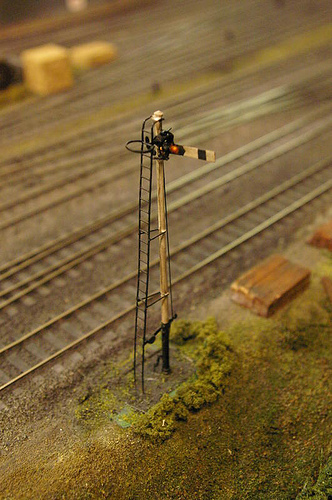
The first signal constructed is a scale 25foot LMS tubular Post and made from the S4.KM1 kit. The first alteration to the kit was to
have the signal lamp operational. I took the lamp from the kit and made a mould of it in “Blue Tak”. The lamp was removed and I inserted a 1.8mm LED where the lamp lens was situated. Next I connected fine insulated wire stripped from an old transformer to one of the legs. Epoxy resin was poured into the mould with the wire and one of the legs protruding from the bottom. When the resin had hardened the new lamp with integral led was removed from the mould and cleaned up with a small file. A small hole was drilled in the side of the signal post where the lamp will be located and the fine wire passed through down the middle of the post. The other leg of the LED is soldered to the post and acts as the support bracket for the lamp. Attached to the underneath of the base of the signal is a small piece of Vero board. Here you connect one
terminal to the signal post and the other to the wire. Now all that remains to be connected for the circuit to work is a fly lead with a 3.5mm jack plug obtainable from Maplins. The Lamp was tested before any other work commenced.
The locating & operating mechanism
The signal post is made up out of a series of brass tubes located into each other. The upper post being 5/32” tube. This fits into the 3/32” base, which then fits into a 1/8” ground tube. This ground tube protrudes through the baseboard and located into a 3/16” mounting tube, which is joined to the mechanism frame (40mm x 40mm plastic angle), this in turn is screwed to the lower baseboard directly under the signal. A cut-out 15 x 25mm is made in the baseboard for the signal and fly lead to pass through. The whole thing is located above the baseboard by strips of Plasticard the same thickness as the signal base.
This is version 4 of the operating mechanism. The previous three systems were all relay operated in one way or another. They all suffered from the same basic flaw. When the signal operated it never appeared life like. The signal arm always moved at what seemed to be 100 mph! On the MERG web site I noticed some technical bulletins on Memory wire with associated circuitry. I contacted the Chairman Paul King and ordered their memory wire pack. This pack includes 1.2 meters of memory wire, and all the associated springs, crimps and terminals with instructions to build a mechanism. The whole thing was mounted on a strip of plastic angle section (40 x 40mm) sold in 3 Metre lengths that I purchased from my local hardware shop for £4.50.
The armature is a length of brass wrapped around a 2mm nut and screwed on to its corresponding bolt so it sits directly below the signal-operating lever. Beside the armature is the backstop. This restricts the movement of the memory wire return spring. Along the bottom is the memory wire in a Teflon catheter. The armature where it comes into contact with the signal-operating lever must be insulated as it is at a constant 5volts and the signal is at zero volts, (being the earth for the lamp). I adjusted the armature so that 2.5mm movement in the memory wire corresponded to the full movement of the signal. This included a small gap between the armature and the signal-operating lever. Memory wire contracts between 3& 4 % of its total length when a current is passed through it. The table below is a calculation of this. In the pictures you can see the electronics involved for each signal.
To operate the mechanism you will require two constant current supplies. One at 5 volts the other at 3.1 volts. The signal lamp is
fed from the 5 volt supply through a 2.1K ohm-limiting resistor. This is discretionary as it controls the brightness of the lamp. The adjustable resistor in the middle of the picture affords some control over the speed of operation of the signal.
The circuit diagram is for all the boards. All components were purchased from Farnell’s. Please note that the two Integrated circuits will need much larger heatsinks if and when more signals are added.
Memory Wire calculations (to the nearest mm.)
Movement MW length.
1.0mm 29mm
1.5mm 43mm
2.0mm 57mm
2.5mm 72mm
3.0mm 86mm
3.5mm 100mm
4.0mm 114mm
4.5mm 129mm
5.0mm 143mm
By Dennis Mulhair, Egham & Staines Model Railway Society, 2003
This Article was written in 2003 to explain the working signals on our previous layout. Working signals to this design will be installed on Colnebourne as time permits.
Runthorne, London Road is the OO finescale layout of the Egham & Staines Model Railway Society (E&SMRS). It started life in the mid 1980’s and was featured in the January 1992 edition of The Railway Modeller and exhibited at the Warley MRC exhibition in 1994. Early in January 2002 the finescale team had a tough decision to make as the layout was getting on in
years and was becoming temperamental in its operation. Either we scrap it or start a modernisation program to bring it up to 21st century standards. After weighing up all the pro’s and con’s we decided on the modernisation program and my job was to renew all the signalling with working units.
From the beginning we decided that all the signals had to be able to be removed so that they could be stored whilst the layout was in transit
to exhibitions. Also they had to operate prototypically with working lamps. As I knew nothing about signalling I contacted Andrew Hartshorne of Model Signal Engineering and asked for his assistance. I supplied him with the layout plan and he in turn drew up a signalling plan. At the same time I purchased two books from him “Signals for the Railway Modeller” by Derek Mundy and “Constructing and operating Semaphore Signals” by Mick Nicholson. Within these two volumes one can gleam all the information required to build and order the required parts from Model Signal Engineering. I am also a member of MERG (Model Electronics Railway Group) and found a mountain of information and help in
building the signals. If you wish to build the operating mechanism enclosed then I strongly recommend joining this group. I am not going to explain the building of the signals just the modifications I have done.
The Signal Lamp
The first signal constructed is a scale 25foot LMS tubular Post and made from the S4.KM1 kit. The first alteration to the kit was to
have the signal lamp operational. I took the lamp from the kit and made a mould of it in “Blue Tak”. The lamp was removed and I inserted a 1.8mm LED where the lamp lens was situated. Next I connected fine insulated wire stripped from an old transformer to one of the legs. Epoxy resin was poured into the mould with the wire and one of the legs protruding from the bottom. When the resin had hardened the new lamp with integral led was removed from the mould and cleaned up with a small file. A small hole was drilled in the side of the signal post where the lamp will be located and the fine wire passed through down the middle of the post. The other leg of the LED is soldered to the post and acts as the support bracket for the lamp. Attached to the underneath of the base of the signal is a small piece of Vero board. Here you connect one
terminal to the signal post and the other to the wire. Now all that remains to be connected for the circuit to work is a fly lead with a 3.5mm jack plug obtainable from Maplins. The Lamp was tested before any other work commenced.
The locating & operating mechanism
The signal post is made up out of a series of brass tubes located into each other. The upper post being 5/32” tube. This fits into the 3/32” base, which then fits into a 1/8” ground tube. This ground tube protrudes through the baseboard and located into a 3/16” mounting tube, which is joined to the mechanism frame (40mm x 40mm plastic angle), this in turn is screwed to the lower baseboard directly under the signal. A cut-out 15 x 25mm is made in the baseboard for the signal and fly lead to pass through. The whole thing is located above the baseboard by strips of Plasticard the same thickness as the signal base.
This is version 4 of the operating mechanism. The previous three systems were all relay operated in one way or another. They all suffered from the same basic flaw. When the signal operated it never appeared life like. The signal arm always moved at what seemed to be 100 mph! On the MERG web site I noticed some technical bulletins on Memory wire with associated circuitry. I contacted the Chairman Paul King and ordered their memory wire pack. This pack includes 1.2 meters of memory wire, and all the associated springs, crimps and terminals with instructions to build a mechanism. The whole thing was mounted on a strip of plastic angle section (40 x 40mm) sold in 3 Metre lengths that I purchased from my local hardware shop for £4.50.
The armature is a length of brass wrapped around a 2mm nut and screwed on to its corresponding bolt so it sits directly below the signal-operating lever. Beside the armature is the backstop. This restricts the movement of the memory wire return spring. Along the bottom is the memory wire in a Teflon catheter. The armature where it comes into contact with the signal-operating lever must be insulated as it is at a constant 5volts and the signal is at zero volts, (being the earth for the lamp). I adjusted the armature so that 2.5mm movement in the memory wire corresponded to the full movement of the signal. This included a small gap between the armature and the signal-operating lever. Memory wire contracts between 3& 4 % of its total length when a current is passed through it. The table below is a calculation of this. In the pictures you can see the electronics involved for each signal.
To operate the mechanism you will require two constant current supplies. One at 5 volts the other at 3.1 volts. The signal lamp is
fed from the 5 volt supply through a 2.1K ohm-limiting resistor. This is discretionary as it controls the brightness of the lamp. The adjustable resistor in the middle of the picture affords some control over the speed of operation of the signal.
The circuit diagram is for all the boards. All components were purchased from Farnell’s. Please note that the two Integrated circuits will need much larger heatsinks if and when more signals are added.
Memory Wire calculations (to the nearest mm.)
Movement MW length.
1.0mm 29mm
1.5mm 43mm
2.0mm 57mm
2.5mm 72mm
3.0mm 86mm
3.5mm 100mm
4.0mm 114mm
4.5mm 129mm
5.0mm 143mm
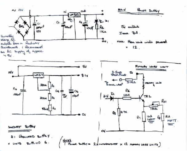
Key to Circuit Diagram.
TR1 BC 337-40
D1 1N4001
C1 100 microfarad 63v
C2,3 & 6 10 microfarad electrolytic 16v
C4 & 5 0.1 microfarad.
BR1 6A, 100v
Z1 red led (and R1 not required for circuit to work)
All resistors 0.25W unless stated.
References.
Model Signal Engineering. http://www.modelsignals.com/
Farnell Electronics. http://uk1.farnell.com/
Model Railway Electronics group. http://www.merg.org.uk/
Technical Bulletins S17/1,G23/1,G22/1,G19/1 & G19/2
The signal diagram supplied by Model Signal Engineering.
